
 |
| Fig:1.1 OSI Model |
A Journey Through the Layers: Understanding OSI Model
In the start when Computer networking comes into play, the computer was typically communicating only the computer of the same brand or manufacturer. For example, if a company decides to take a solution from IBM they have to purchase the complete from IBM. Or if they go for any ABC company solution they had to take a complete solution of this company. There was no way for communication between two different manufacturer systems. With the growing need for communication and to better facilitate the companies in the late 1970s (ISO) International Organization for Standardization created the (OSI) reference model, which breaks the barrier between different manufacturers.
The OSI model was there to guide vendors to create interoperable devices for network and software in the form of protocols so that they could communicate with each other whether they belong to different manufacturers. It was just a start of good not complete but a great goal.
The OSI reference model is the primary architectural model which defines the way that how data or network information from an application of one computer communicate through the network media to an application of another computer placed somewhere else means on another network.
To accomplish the whole OSI reference model divide this approach into layers. In the coming discussion, we will discuss the Layered approach in detail that how it works, and how it helps to troubleshoot in internetworks.
Layered model
A layered model is basically a conceptual framework that described that how communication between two or more entities should take place. To make that communication effective it makes the logical groups of all processes these groups are called layers and the whole design is called layer architecture.
Let’s try to understand this layered approach (reference model) with an example: You want to start a business with your friends. First of all, you will arrange a meeting with all of your business partners (your friends) so that you will define the job roles that who will be responsible for what, in which order the whole task will be done, and how these all will be related to each other. Then after defining all tasks you will group them department-wise. Like other companies have purchase department, inventory department, and shipping department. Now in this way each department has its own tasks, its own staff and they completely focus on their tasks to make them complete on time. The same thing has been done in the reference model each layer has its own task, the process of working, and totally responsible for only its own tasks only. During your meeting, you prepare the notes of the whole meeting or discussion or may record the whole process for further discussion. As same in a layered approach, all the tasks noted layered wise to better facilitate and further discussion of operating standards it will serve you as your reference model and also business model according to the example of business we discuss.
Now your business comes in running, all of your company department heads are equipped with a blueprint section for their relevant department, they will need to develop practical ways to carry out assigned tasks. These all procedures need to closely follow the standard operating procedures. Each of the different procedures should note in your manual for different reasons and all have their own importance and way of implementation. Now if make a partnership or got another company, in this case, all of the business protocols and business plans should be matched or at least be compatible between both companies. In the same way, all software developers use a reference model to understand the process of communication and the functions that need to be performed in one layer. If you want to develop a protocol for a specific layer, then you should only care about the functions of that respective layer, not others. Other layers will take care of their own. Now here is a technical term that is binding. The processes of communication that are related to each other, grouped with each other.
Why reference model is beneficial
First of all, the reference model allows the different networks providers to work together. The layered model divides the processes into smaller and simpler tasks in this way it will be easy to accomplish the big by completing the small ones. The task could be the improvement of any component development, it could be a new design and it could also be troubleshooting. It enables multi-vendors to develop a component by following the standard. It helps industry standardization by defining what functions are involved or not in each layer of the reference model. In this way, it allows different network hardware and software to communicate with each other. By using a layered model, it prevents the changes in one layer from disturbing other layers.
The OSI reference model in detail
One of the greatest achievements of OSI model specification is, it assists in data transfer between different hosts. This means it allows us to communicate between Unix, a Windows PC, or a Mac. Actually, OSI is not a physical model it is a set of guidelines that are used by application developers when they develop and implement the application to run them on the network.
For the networking domain, it gives a framework to create and implement the networking standards, devices, and internetworking schemes.
The OSI reference model has two groups including seven different layers. The first group also called top layers has three layers that completely focus on the communication of applications within the end stations. The second group also called bottom layers of four layers provides the standards way of transmission from end to end.
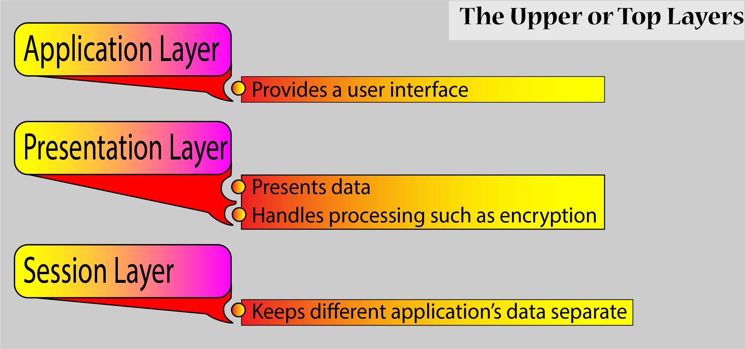
Figure-1.2 shows the group of three top layers and their functions of the OSI model. The top three layers are only responsible for the communication of applications between hosts. None of them knows anything the computer networking or networks.
 |
| Fig:1.2 OSI Model upper three layers |
Figure-1.3 shows the group of four bottom layers and their functions of the OSI model. The bottom Four layers are completely responsible for the networking they define that how data will move or be transferred through a network cable (physical wire) or network switches and routers. The rebuilding of the data stream which is being transmitted from the transmitting host to the device of the destination host’s application is also done by these bottom layers.
 |
| Fig:1.3 OSI Model bottom four layers |
Before going to in detailed discussion I want to mention some of the network devices that operate at all the seven layers of the OSI reference model.
- (NMSs) Network Management Stations
- Web and application servers
- Gateways but not default gateways
- Network hosts
Summary of the functions which are defined at each layer of the OSI reference model could be seen in Figure-1.4:
 |
| Fig:1.4 OSI model layer functions |
The Application Layer (Layer Seven)
The Seventh Layer of the OSI reference model, The Application Layer is the layer where the computer user communicates to the computer. To completely understand the application layer let discuss an example of Internet Explorer. This layer comes into play only in that case when it seems that the need for access to the network is required soon. For the time being, if you remove or uninstall TCP/IP, Network interface card and so on you can still view the HTML document by using Internet Explorer (IE) without any problem. But all this would not work if you try to view the HTML file which must be retrieved using HTTP or FTP or maybe TFTP. It is because the IE needs to access the Application layer to respond to this request. In that case actually the Application Layer act as an interface between the application program. As we remove the way going down to the next layer through the protocol stack. Mean IE needs to interface with the protocol of the Application layer when it needs to communicate with remote resources.
It is the responsibility of The Application layer to identify and establish the availability of partners who are intended to communicate and also determine the existence of resources for intended communication.
The tasks are much important as sometimes computer applications required more resources other than desktop resources, for this, they often unit the components which are used for communication from more than one application of network. The examples are transferring of files, email, enabling the remote access, management activities of the network, client/server processes.
To better understand The Application Layer, keep in mind that it acts as an interface between the actual applications.
The Presentation Layer (Layer Six)
As per the name of the Presentation layer, it presents data to the Application layer. It is also responsible for the translating of data and code formatting. For successful transmission of data this layer changes the data in a standard format and transmit because almost all computers are configured to receive data in this generical format after receiving they convert it back into its native format to make it readable. An example is EBCDIC to ASCII.
The Session Layer (Layer Five)
The Session as gets from its name it creates the session or in other words it set up the connection, manage the connection, and after completing the task breaks or tear down the connection between the entities of the Presentation layer at both side receiving and destination computers.
The Transport Layer (Layer Four)
The Network Layer (Layer Three)
The Data Link Layer (Layer Two)
Note:
Here I want to mention an important thing. The Network Layer didn’t concern with the physical location of the destination host it was only concerned with the networks in which the destination device was located. It just provides the best path to reach that network.
It is the responsibility of The Data Link Layer for the actual identification of each that resides on a local network. Layer 2 devices maintain the mac-address-table to keep the record of every connected device in LAN. Switches and Bridges are the popular devices of The Data Link layer.
The Physical layer (Layer One)
Finally, we reach the end but actually the start of one end The Physical Layer. Two things are done by this layer it sends bits and receives bits in the form of 1 and 0, a Morse code with numerical values. This layer actually communicates directly with different physical media than the actual communication media. All these different media handle the bits in their own ways. Some of them handle in form audio tones, while some of the changes in voltage from high to low and low to high. Each type of media required specific protocols to describe and exact bit patterns to be used. Network Cables and Hubs are all laid in as the media of the Physical Layer.